博文

目前显示的是 一月, 2021的博文

100G QSFP28 Optical Transceiver Comparison

  Nowadays, the trend for 100G Ethernet network is bullish and inevitable. Thus, the demands for 100G modules are becoming greater and greater that account for a relatively high proportion of network construction costs. Among various 100G optical transceivers that are capable of connecting 100G traffic, the 100G QSFP28 optical transceiver is the most preferred module for smaller size and lower power consumption. What are 100G QSFP28 optical transceivers? What are the differences between them? How do we choose 100G QSFP28 optics? Today, we will make a comprehensive comparison of 100G QSFP28 optical modules for you.   What Is 100G QSFP28 Optical Transceiver? The 100G QSFP28 optical transceiver is designed for 100 Gigabit Ethernet, EDR InfiniBand, or 32G Fibre Channel. It generally has the exact same footprint and faceplate density as 40G QSFP+. Just as the 40G QSFP+ is implemented using four 10Gbps lanes, the 100G QSFP28 module is implemented with four channels of high-speed diffe

40G QSFP+ Module is a Great Progress for Telecom Industry

  are you still worrying about your slow network speed? No, there is a high speed transceiver. 40G QSFP+ transceivers make you enjoy the better transmission communications. As an essential component to support 40G network, QSFP+ modules which allow data rates of 4×10 Gbit/s to be emerged. This article is to introduce the 40G QSFP+ modules, include 40G QSFP+ cables and 40G QSFP+ transceivers. fiber-mart.com supplies high quality QSFP+ transceivers which are used primarily for short reach applications in switches, routers, and data center equipment.   What’s 40G QSFP+ Module? The 40G QSFP+ module is a compact, hot-pluggable transceiver used for data communications applications. It supports Serial Attached SCSI, 40G Ethernet, QDR (40G) and FDR (56G) Infiniband and other communications standards. Compared with SFP+ modules, QSFP+ transceiver increases the port-density of 3-4 times.   The 40GBASE-SR4 is based on MMF (Multi-Mode Fiber) optic cable which is cheaper than SMF (Single

Cisco 10G Ethernet SFP Modules

  It is well known that Cisco is a worldwide leader in the telecommunication industry. Cisco products and services are very welcome among the users, which ranges from application networking services, optical networking, to routers, switches, interfaces and modules, etc. This paper will introduce Cisco 10 Gigabit Ethernet SFP modules . 10 Gigabit Ethernet (10GE, 10Gbe, or 10 GigE) is a group of computer networking technologies for transmitting Ethernet frames at a rate of 10 gigabits per second (10 billion bits per second). It was first defined by the IEEE 802.3ae-2002 standard. Below is part of the 10 Gigabit Ethernet standards related to this topic. According to the standards, Cisco SFP modules for 10 Gigabit Ethernet have different types, such as Cisco SFP-10G-LRM module, Cisco SFP-10G-ER module, Cisco SFP-10G-ZR module, Cisco SFP-10G-SR module and Cisco SFP-10G-LR module, etc. Below will introduce two most common Cisco SFPs: Cisco SFP-10G-SR and Cisco SFP-10G-LR. Cisco SFP-10G

Brief introduction of 25G SFP28 Transceiver

  With the evolution of 5G technology, equipment providers are responding with 25Gbps edge devices that require more bandwidth than can be provided on a traditional 10Gbps interface. 25G SFP28 transceivers are the critical player among them. They come in various types that cover different transmission distances. 25G SFP28 Transceiver Type and Applications 25G Standard SFP28 Transceiver Module 25G SFP28 transceiver module can be classified into Short-Range (SR), Long-Range (LR) transceivers and Extended-Range (ER) transceivers in terms of the transmission distance. The SFP28 SR is mainly used with OM4 multimode fiber to transfer data over a short distance (up to 100m), while the SFP28 LR is mainly used with OS2 single mode fiber for long distance transmission (up to 10km) and the SFP28 ER used with OS2 single mode fiber can realize at most 40km transmission. They can be plugged into data center, campus and service provider switches and routers to provide high speed 25Gbps connect

How does cold weather affect fiber optic connectors and cables?

  At the speed of light, it carries huge quantities of data at the speed of light – optical fibre is everywhere. Flexible and thin, around the thickness of human hair, glass or plastic fibre is super-fast.   Overtaking copper wire as the medium of choice, fibre carries data as pulses of light. Because of its lower cost, its faster speed and the fact it’s less bulky is the reasoning behind the shift. Optical fibre is also harder to hack than copper, making it more secure and safer because it doesn’t generate heat in the same way copper does.   It does, however, come with its own challenges. Installation and management must be carefully managed because of the delicate nature of optical fibre. Any amount of grease, dirt or moisture can affect the transmission of light, even the tiniest of specks. Although the actual fibres themselves are protected by and acrylic layer, the connectors joining each fibre can be vulnerable in harsh environments.   This is true in outdoor applicat

How to use fast connectors?

The wide application of the fiber to the home (FTTH) promotes the rise of the optic connector. This product has the characteristics of small size and fast connection, and caused small loss, high stability, it’s essential fiber connection devices for fiber system. Today will introduce the use instruction of fiber fast connector.   About fiber fast connector Fiber fast connector is a kind of innovative field end connector, currently the fiber fast connector can be terminated with a diameter of 250μm, 900μm, 2.0mm and 3.0mm SM fiber and MM fiber on the market.     Features and applications of fiber fast connector Main features Good stability Small insertion loss Low use cost Installation speed is very fast Installation and maintenance is very simple   Main applications Optical fiber communication applications Fiber to the home (FTTH) applications Wire TV application   Use steps of fiber fast connectors Although the use of fiber fast connector is very

How to choose a fiber optic adapter?

图片
  Due to the wide variety of fiber optic adapters and the similar appearance of fiber optic adapters from different vendors, you may not know how to choose. In general, you should consider the following two tips when choosing a fiber optic adapter.   Fiber Cable Type If the fiber adapter needs to be connected to the same fiber cable type and connector, a fiber optic adapter with a square, rectangular or circular interface can be used. If the type of cable to be connected is different, a hybrid fiber adapter is required. This hybrid fiber adapter can connect any two types of fiber patch cords together. Due to the wide variety of hybrid fiber optic adapters, it is important to know what type of cable to connect before purchasing.   The Sleeve Material of fiber adapter Alignment sleeve is the most important component of fiber optic adapters. Some manufacturers choose metal as the material for the alignment bushings, but ceramic-made fiber optic adapters have proven to work muc

What is Fiber Optic Adapter

图片
  Fiber optic adapters (also known as Fiber couplers, Fiber Adapter ) are designed to connect two optical cables together. They have a single fiber connector (simplex), dual fiber connector (duplex) or sometimes four fiber connector (quad) versions. The optical fiber adapter can be inserted into different types of optical connectors at both ends of the optical fiber adapter to realize the conversion between different interfaces such as FC, SC, ST, LC, MTRJ, MPO and E2000, and is widely used in optical fiber distribution frames (ODFs) Instruments, providing superior, stable and reliable performance.   Features of Fiber Optic Adapter The optical fibers are connected by an adapter through its internal open bushing to ensure the maximum connection between the optical connectors. In order to be fixed in a variety of panels, the industry also designed a variety of finely fixed flange.   Transformable optical adapters are available with fiber optic connectors of different interface

Applications of EDFA

图片
  EDFA Following are the typical application of Erbium doped fiber amplifiers.   1. Power Amplifiers   2. In-Line Amplifiers   3. Pre Amplifiers   4. Loss Compensation in Optical Networks   Power Amplifier: Power amplifiers (also called booster amplifiers) are placed directly after the optical transmitter. In this application, EDFA’s need to be able to take a large input signal and provide maximum possible output level. The noise is not a major concern at this stage as the incoming signal has a large signal to noise ratio. Typical EDFA power amplifiers have an output of around 100mW.   In-Line Amplifier: The in-line amplifier (also called in-line repeater) takes a small input signal and boost its for retransmission down the fiber and thus it replaces the repeater within a long communication line. At this stage, noise is a major concern because the signal is weak.   Pre-Amplifier: Modern telecommunication systems are pushing the practical limits of rece

Detailed Introduction of Optical Amplifiers

图片
Optical Amplifier   WHAT IS OPTICAL AMPLIFIER? Optical Amplifier is a device referred to as a repeater accomplished the re-amplification where optical signal is attenuated when traveling through an optical fiber in long-distance applications. While the technology available today eliminates the need for repeaters, the optical amplifiers are now used instead of repeaters. An optical amplifier can amplify optical signal directly without electric and electric optical transformation. The originally dominating application of fiber amplifiers was in optical fiber communications over large distance, where signals need to be periodically amplified, with the developments of optical amplifier, there are more and more types to choose for customers' different needs, even some high-power fiber amplifiers are now used in laser material processin.   Tips: A repeater is basically a receiver and transmitter combined in one package. The receiver converts the incoming optical energy into electr

How We Designed the Low Profile Optical Switch Differently

  On the previous blog we specifically spoke about the differences between optical switches and mechanical switches. Simply put, an optical switch differs from a mechanical switch in that they use light for actuation instead of a metal to metal connection, which enhances the speed and act way faster than a mechanical switch.   Apart from the faster actuation, optical switches offer a couple more benefits. Some of those are resistance to moisture, more reliable, ultra-low latency, and a better and longer lifespan.   At fiber-mart.com, we have purposefully designed our own brand-new fiber-mart.com low profile optical switch to use for the K3 keyboard. We constantly strive to push innovation in all our fiber-mart.com keyboards. Our latest innovation is our low profile optical switches and now we want to share the design process that went into these switches.   The fiber-mart.com Low Profile Optical Switches Design Unlike high profile or standard optical switches in the keyb

The Knowledge of Optical Switch

Optical networking technology has grown rapidly and helped solve the problem of increasing demand for higher transfer data rates and bandwidths. In optical networks, optical fiber is the fundamental medium of transmission, but functions like switching, signaling and processing are accomplished electronically. To achieve conversions between optical signals and electrical signals, optical switches are naturally developed. What is an optical switch? This post will offer some basic information about optical switches.   Introduction In telecommunication, an optical switch is a switch that enables signals in optical fibers or integrated optical circuits (IOCs) to be selectively switched from one circuit to another. An optical switch may operate by mechanical means, such as physically shifting an optical fiber to drive one or more alternative fibers, or by electro-optic effects, magneto-optic effects, or other methods.   Types of Optical Switches An optical switch is simply a swi

How to test fiber optic splitters or other passive devices

A fiber optic splitter is a device that splits the fiber optic light into several parts by a certain ratio. For example, when a beam of fiber optic light transmitted from a 1X4 equal ratio splitter, it will be divided into 4-fiber optic light by equal ratio that is each beam is 1/4 or 25% of the original source one. An Optical Splitter is different from WDM. WDM can divide the different wavelength fiber optic light into different channels. fiber optic splitter divides the light power and send it to different channels.   Most Splitters available in 900um loose tube and 250um bare fiber. 1*2 and 2*2 couplers come standard with a protective metal sleeve to cover the split. Higher output counts are built with a box to protect the splitting components.   Testing a coupler or splitter (both names are used for the same device) or other passive fiber optic devices like switches is little different from testing a patch cord or cable plant using the two industry standard tests, OFSTP-14

What is a PLC Splitter and How Does a PLC Splitter Work?

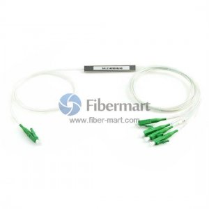
What is PLC Splitter? PLC splitter known as Planar Lightwave Circuit is used for dividing one or two light beams to multiple light beams uniformly or combining multiple light beams to one or two light beams. It has a passive component with special waveguide made of planar silica, quartz, or other materials. It is mainly applicable to PON (EPON, GPON, BPON, FTTX, etc.) to combine with the MDF (main distribution frame) and the terminal equipment to branch the optical signal.   As a micro-optical device PLC splitter uses optical to split the input signal into various outputs. PLC splitter mainly adopts silica glass as the material of the lightwave circuit and accepts different types of polished finishes. They can be categorized into different types including bare PLC splitters, blockless PLC splitter, ABS PLC splitters, LGX box PLC splitters, mini plug-in type PLC splitters, tray-type PLC splitters, and 1U rackmount PLC splitters. PLC splitters can offer splitting ratio up to 1*64,

Learning the Different Coating Stripping Methods

  The cladding power stripper also referred to as the multimode optical power stripper is designed for amplifier applications and high power fiber laser. It is an ideal device for ASE, residual pump power stripping, core modes that have escaped from double cladding fibers inner cladding while ensuring preservation of single power minimal degradation and beam quality (M2). Single power that is reflected into the inner cladding may also be stripped out too.   The handling capability of the stripping power goes to 800W or at times may be even higher   Stripping the Coating   The fibers that most reputable companies supply all come with a standard acrylate single layer coating or, in some such as the high power products, a coating that is high temperature enduring. In comparison to dual layer coatings, the coatings that are single layer are more brittle and smooth. The coating can be removed readily using the conventional tools for fiber stripping such as the Fitel S-210 Clauss or

Discussing Multiple Aspects of a Standard Cladding Power Stripper

Fiber laser systems have many advantages over other laser systems, including high beam quality, high conversion efficiency, cost-effectiveness, and lightweight. They have been widely applied in areas, such as optical sensing, medical devices, advanced industrial processing, and military defense. With the development of the double cladding fiber technology and laser diode pump technology, the output power of the fiber laser systems has been increased rapidly. However, the unwanted light and optical power increase, due to which the utilization of cladding power stripper becomes essential.   The actual and prime sources of the unwanted light transmitting in the cladding can be divided into 3 sections   Amplified spontaneous emission (ASE)   Residual pump light which is often there at the gain fiber’s end   Core light being reflected into the cladding or leaking into it   All the above-described unwanted light sources are actually spread throughout the chain of componen

How Much Do You Know About PLC Splitter?

图片
 What Is PLC Splitter? PLC splitter, also called Planar Waveguide Circuit splitter, is a device used to divide one or two light beams to multiple light beams uniformly or combine multiple light beams to one or two light beams. It is a passive optical device with many input and output terminals, especially applicable to PON (EPON, GPON, BPON, FTTX, etc.) to connect the MDF (main distribution frame) and the terminal equipment and to branch the optical signal.   PLC splitter PLC splitter provides a low-cost light distribution solution with high stability and reliability. PLC splitters can offer a splitting ratio of up to 1x64, which is generally higher than the splits of FBT splitter that another common type of optical splitter.   PLC Splitter Manufacturing Technology PLC splitter is based on Semiconductor technology. As its name shows, PLC splitters are manufactured by planar waveguide circuit technology. PLC splitter design consists of one optical PLC chip and several optic